-
CN
-
Service Hotline
+8618129931046 Mr. Liao


Time:2025-08-05 Views:1

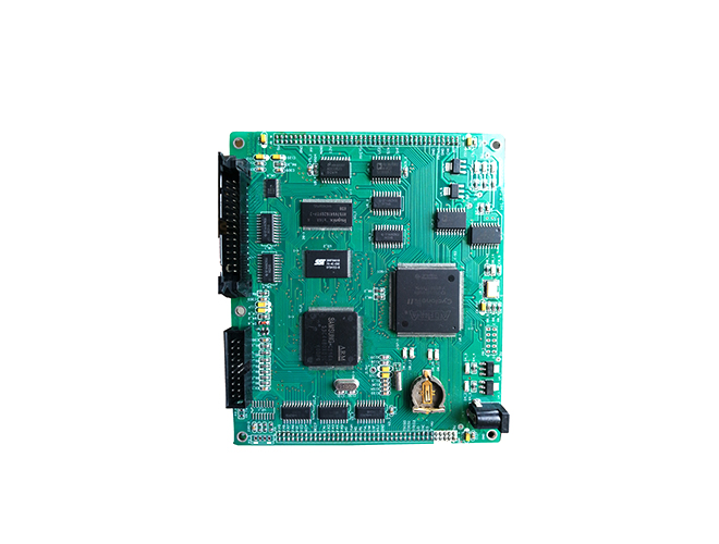
A motor driver PCB (Printed Circuit Board) is a specialized circuit board designed to control the operation of electric motors, converting low-voltage control signals into high-power outputs that drive motors in applications ranging from industrial machinery to consumer electronics. These PCBs integrate motor driver ICs, power management components, and protection circuits to regulate motor speed, direction, and torque while ensuring safe and efficient operation.
The core component of a motor driver PCB is the motor driver IC, which varies based on the motor type—DC motors, stepper motors, or brushless DC (BLDC) motors. For example, H-bridge ICs (such as L298N or DRV8825) are common for DC and stepper motors, enabling bidirectional control and current regulation. BLDC motors require more complex drivers with sensor interfaces (Hall effect or encoder) to synchronize commutation, often using dedicated ICs like DRV10983. These ICs are paired with power MOSFETs or transistors to handle high currents, ranging from a few amps for small motors to hundreds of amps for industrial models.
Thermal management is critical, as motor drivers dissipate significant heat during operation. Motor driver PCBs use thick copper traces (2-4 oz/ft²) to minimize resistance and heat generation, while heat sinks or thermal vias (connecting top and bottom copper layers) dissipate heat to the ambient environment. Some designs include thermal pads on driver ICs, directly bonding to the PCB’s copper plane for efficient heat transfer—essential for preventing overheating in enclosed spaces like robotic arms or automotive systems.
Protection features are integral to prevent damage from electrical faults. Overcurrent protection (via fuses or current-sense resistors), overvoltage protection (Zener diodes), and reverse polarity protection (Schottky diodes) safeguard both the PCB and the motor. Undervoltage lockout (UVLO) ensures the driver shuts down if the supply voltage drops below a safe threshold, preventing unstable operation.
Layout optimization is key for performance. Power traces are routed separately from control signals to avoid electromagnetic interference (EMI), which can disrupt sensitive control circuits. Ground planes are used to reduce noise, and high-current paths are kept short to minimize voltage drops. For high-frequency BLDC motor drivers, proper grounding and decoupling capacitors (placed near ICs) stabilize voltage levels and reduce ripple.
Motor driver PCBs are used in diverse applications: robotics (controlling joint motors), CNC machines (stepper motor precision), electric vehicles (window regulators), and household appliances (dishwasher pumps). Their design must balance power handling, thermal efficiency, and protection to meet the specific demands of each motor type and application environment.